Since its release in 2012, I’ve been a big fan on the Raspberry Pi microcomputer. I’m currently running it as a low-power file- and print-server at home, and two Computer Science Honours Students that I helped supervised used a Raspberry Pi to prototype Cloudlets: ad-hoc, hyper-local instantiations of the cloud that are independent of cloud infrastructure but provide similar services.
More recently I’ve been working on a research project at Swansea University and in collaboration with IIT Bombay to design, prototype, deploy, and evaluate smart speakers in public contexts in Dharavi, Mumbai. We prototyped two different speakers, one powered by Google Assistant that delivers instant answers, and the other powered by human intelligence, where questions are forwarded to a crowd of people providing answers.
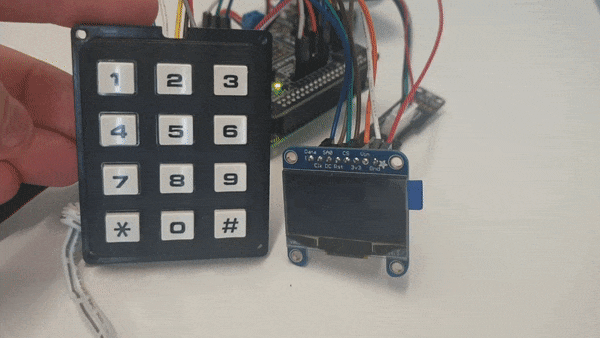
For the later, human-powered prototype we needed an easy-to-use and robust way for people to query the answers as these would only become available after about a 10 minute delay. We settled on a design that combines a 3x4 Phone-style Matrix Keypad with an 128x64 OLED Dot-matrix Display with an SSD1306 driver. When the user asks a question they are given a 4-digit code (e.g. 1234), which they can subsequently use to query their answer. To query an answer the user, keys in the numbers in their four digit code, which is displayed as they type it. These words don’t really describe it properly, do they? Perhaps, then, an animation will help.
While the keypad interaction is simple, the implementation is not. The thing about buttons is that they tend to bounce. That is they register more than one press per press. To understand why, lets look under the hood of the 3x4 Matrix Keypad we used for the project.
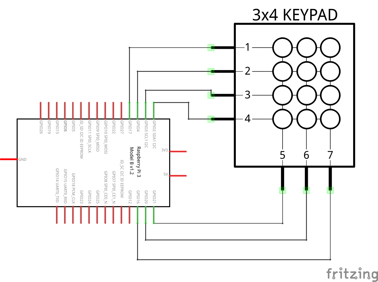
The keypad is connected using seven pins. The first pin is connected to the keys in the first row 1, 2, 3; the second pin to keys 4, 5, 6; the third to keys 7, 8, 9; and the fourth to keys *, 0, #. The next three pins are connected to the three columns of the keypad, namely 1, 4, 7, * (pin five), 2, 5, 8, 0 (pin six); and 3, 6, 9, # (pin seven). We then connect the four row pins & three column pins of the keypad to seven GPIO – General Purpose Input & Output – pins on the Raspberry Pi.
So what then happens, when the user presses button 3. Since the first pin is connected to keys 1, 2, 3 – highlighted in blue – and the seventh pin is connected to keys 3, 6, 9, # – highlighted in red – pressing button 3 closes a circuit between the first pin and the seventh pin. And it is this event we can detect on the Raspberry Pi through it’s GPIO – General Purpose Input and Output – pins.
The GPIO approach
The general process for detecting when a key is pressed is as follows:
- Setup column pins as digital outputs and set high (voltage).
- Setup row pins as digital inputs with pull-up resistors (inputs are set to high).
- Set outputs (column pins) to low, one at a time.
- When a button is pressed, the input becomes low at a particular row.
Since we know which column output was set to low and which row input was measured as low, we simply lookup and return the key at that particular row & column. In the case of pressing 3, the input at the first row pin would be measured as low, once the third column pin was set to low. The following video illustrates the process in more detail. The biggest problem with this approach is that it doesn’t account for button bounce. Buttons sometimes generate spurious open/close transitions when pressed, due to mechanical and physical issues: these transitions fool the program as it can interpret a single press as multiple presses in a very short time.
I also find that whenever I do this type of low level programming, it is easy for errors and unaccounted side effects to sneak in. As I spend most of my time designing and developing Android apps, I’ve become more accustomed to high-level, event-driven and functional reactive programming paradigms. Fortunately the Linux kernel has drivers for a variety of different input devices as well as for common low-level peripheral interfaces such as SPI, I2C, and in our case, generic GPIOs. The kernel also has mechanisms, such as the generic input event interface evdev, to surface events generated in the kernel to programs. So why re-invent the wheel. Paradoxically, in my pursuit of abstracting and modeling keypresses as higher-level events, I found myself drilling down to low-level abstraction level of the Linux kernel.
The kernel driver approach
Luckily there is a GPIO matrix keypad driver, which is compiled and shipped as a module on recent kernels for the Raspberry Pi. With a USB keypad you can just plug into a computer and start using it immediately. But to enable the driver for the GPIO matrix keypad, we need to create a device tree overlay file suited to the given keypad. In this case, the device tree had to be configured with:
- the specific GPIOs used as row lines;
- the specific GPIOs used as column lines;
- and a keymap that maps row, column positions to keycodes
The first two properties are simply enumerations of the GPIO used to connect the keypad to the Raspberry Pi. As we were prototyping a smart speaker, we connected a Google AIY Voice HAT (Version 1) to the Raspberry Pi using it’s 40-way header. The Voice HAT uses 16 GPIO pins, so we had to restrict ourselves to a limited number of available pins. We chose to connect GPIOs 17, 27, 22, & 26 to the keypad row lines. On the Voice HAT these are labeled as Driver 1, 2, 3 and Servo 0, respectively. We then connected the keypad column lines to GPIOs 13, 12, & 24, which are labeled as Servo 2, 4, and 5 on the Voice HAT. We can then plug these row and column GPIOs into the device tree overlay:
row-gpios = <&gpio 17 0
             &gpio 27 0
             &gpio 22 0
             &gpio 26 0>;

col-gpios = <&gpio 13 0
             &gpio 12 0
             &gpio 24 0>;
The keymap is slightly more complicated. It is an array of packed 1-cell entries containing the equivalent of row, column and linux key-code. For example Button 8 can be found in row 2 and column 1 – that is if we start counting at 0 instead of 1. We then need to lookup the keycode for the number 8 in the input-event-codes.h kernel header file. The closest match in our case is #define KEY_KP8 72. So ‘Keypad 8’ is defined as 72. However the device tree keymap requires the keycode in hexadecimal, rather than decimal form. This is a simple conversion using an online tool or the command line:
> printf '%x\n' 72
48
With all this information in place, we can then start to assemble the corresponding entry for button 8:
0x2010048 = Row 2, Column 1, Keycode 48 (hex) = 72 (decimal) = KEY_KP8
Or for button 3:
0x0020051 = Row 0, Column 2, Keycode 51 (hex) = 81 (decimal) = KEY_KP3
Following this pattern we can assemble the full keymap and we end up with the following device tree overlay:
/dts-v1/;
/plugin/;
 / {
   compatible = "brcm,bcm2835", "brcm,bcm2708", "brcm,bcm2709";

    fragment@0 {
     target-path = "/";
     __overlay__ {
      MATRIX3x4 {
       compatible = "gpio-matrix-keypad";
       debounce-delay-ms = <10>;
	   col-scan-delay-us = <10>;

       row-gpios = <&gpio 17 0
                    &gpio 27 0
                    &gpio 22 0
                    &gpio 26 0>;

       col-gpios = <&gpio 13 0
                    &gpio 12 0
                    &gpio 24 0>;

       linux,keymap =
        <0x000004F   // row 0, col 0, 4F = 79 = KEY_KP1
         0x0010050   // row 0, col 1, 50 = 80 = KEY_KP2
         0x0020051   // row 0, col 2, 51 = 81 = KEY_KP3

         0x100004B   // row 1, col 0, 4b = 75 = KEY_KP4
         0x101004C   // row 1, col 1, 4c = 76 = KEY_KP5
         0x102004D   // row 1, col 2, 4d = 77 = KEY_KP6

         0x2000047   // row 2, col 0, 47 = 71 = KEY_KP7
         0x2010048   // row 2, col 1, 48 = 72 = KEY_KP8
         0x2020049   // row 2, col 2, 47 = 73 = KEY_KP9

         0x3000037   // row 3, col 0, 37 = 55 = KEY_KPASTERISK
         0x3010052   // row 3, col 1, 52 = 82 = KEY_KP0
         0x3020062>; // row 3, col 2, 62 = 98 = KEY_KPSLASH (there is no KP_#)
      };
     };
    };
   };
Next we need to compile the device tree overlay into a binary file. This binary file does not need to be ‘architecture aware’, so you can use a recent dtc compiler on the Raspberry Pi, or any computer, to produce the binary:
sudo apt-get install device-tree-compiler
dtc -W no-unit_address_vs_reg -I dts -O dtb -o 3x4matrix.dtbo 3x4matrix.dts
Then copy the resulting binary – 3x4matrix.dtbo – to the boot partition /boot/overlays/3x4matrix.dtbo. And finally, enable the overlay in the boot configuration by adding the following line to /boot/config.txt:
dtoverlay=3x4matrix